How to install Euro Modular Smart Lock - Step by step
BLACK X Smart locks provide enhanced security and convenience, allowing you to control access to your home or office with ease. Whether you're upgrading an existing lock or installing a new one, this guide will walk you through the process of installing a Euro Profile Smart Lock efficiently and correctly.
By following these step-by-step instructions, you'll ensure a secure and hassle-free installation. Let's get started!
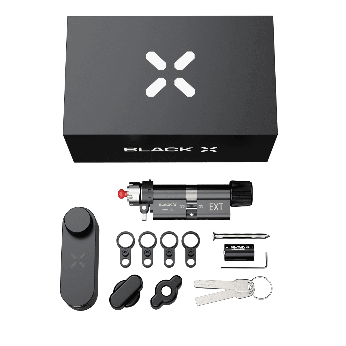
Step 1: Unbox and prepare components
Before installation, open the package and identify all components. Lay them out for easy access.
Hardware components:
BLACK X Euro Profile Smart Lock (1x)
Euro profile door cylinder (1x)
M5x70mm Cylinder Screw (1X)
Mechanical Access Keys (2x)
Box 1
CR2 3V battery (1x)
Allen key (1x)
M5x60mm Cylinder Screw (1X)
Cylinder extensions (4x)
Box 2
Included in the box:
Extra Grip External Knob (1x)
Extra Grip Internal Knob (1x)
Spare Cylinder Screws (4x)
Step 2: Removing the old cylinder
Locate the Mortise Plate: Identify this plate on the door's edge where the door meets the frame.
Unscrew the Cylinder: Locate the screw on the mortise plate that secures the cylinder. Use a suitable screwdriver to carefully unscrew and keep the screw safely for later use.
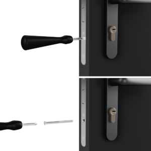
Step 3: Extracting the Cylinder
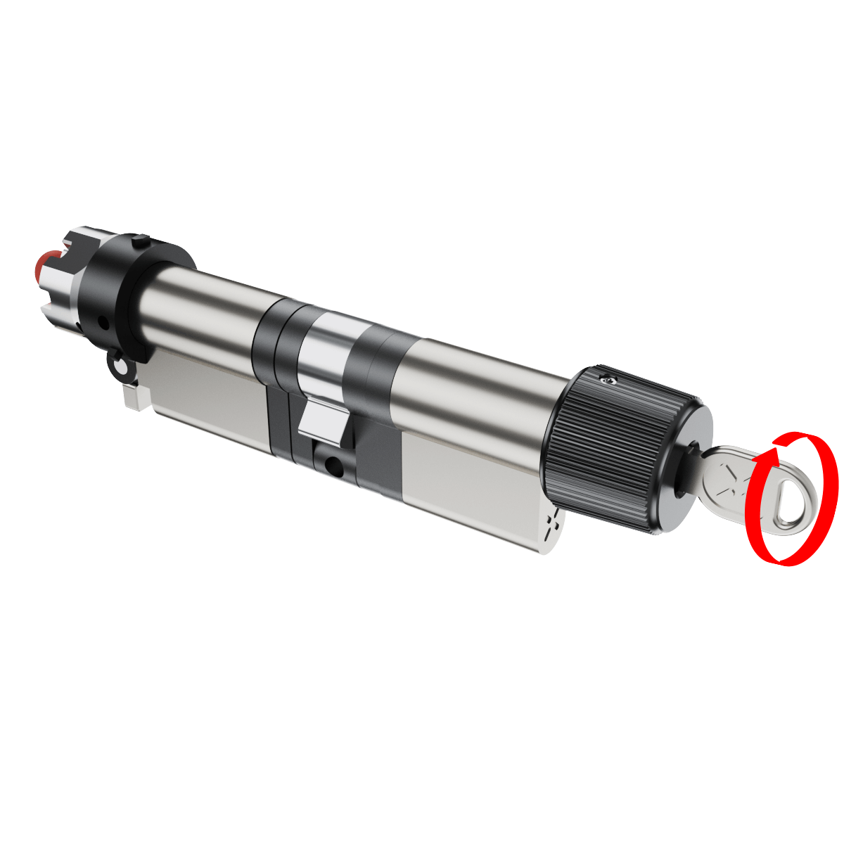
Insert the Key: Fully insert the original key into the cylinder.
Align the Cam: Rotate the key to align the cam with the body of the cylinder, ensuring it can be removed.
Remove the Cylinder: With the cam properly aligned, gently pull the cylinder out from its housing.
Note: if you encounter resistance, recheck the cam alignment.
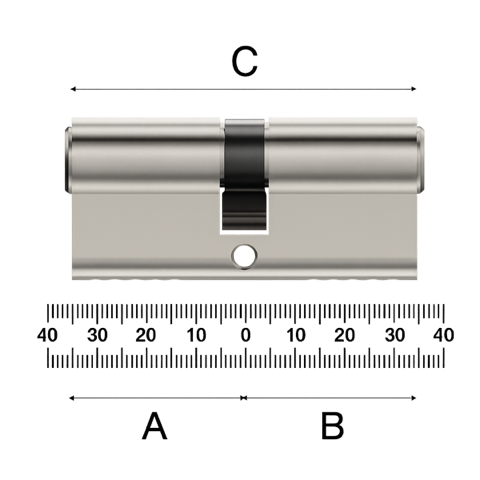
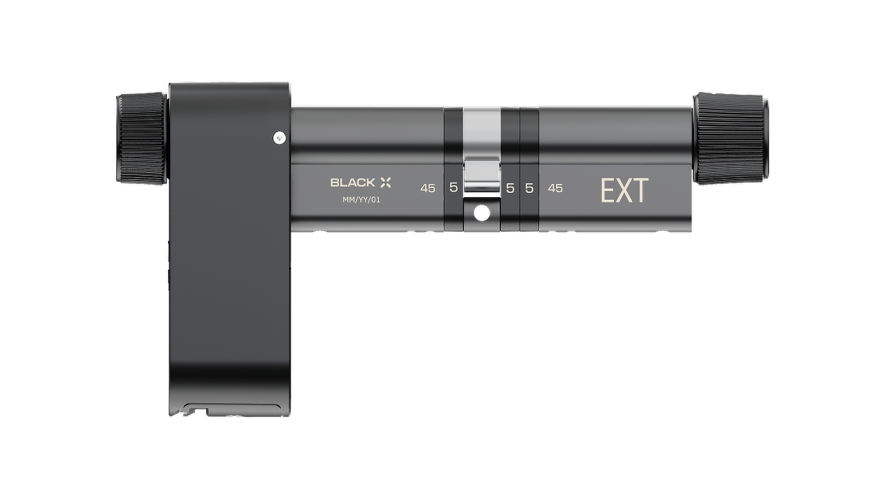
Step 4: Measuring the Previous Cylinder
The modular cylinder can be extended by up to 20 mm in total, allowing a maximum of 2 × 5 mm (10 mm) per side.
Before installation: Use a measuring tool to determine the exact cylinder length required. Refer to the diagram and measure:
A – From the inside edge to the center (screw hole)
B – From the outside edge to the center (screw hole)
C – Total length (end to end)
Based on your measurement, decide how many extensions are needed on each side for the next step.
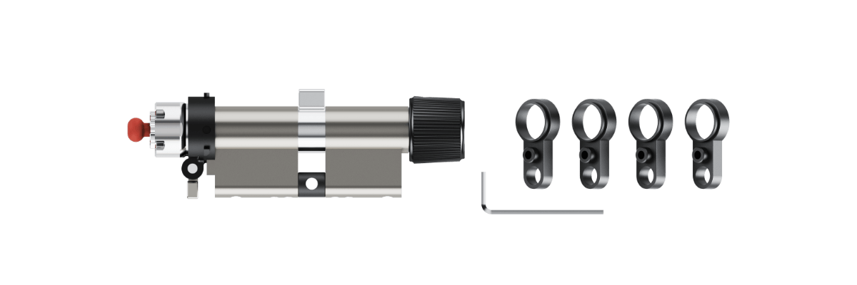
Step 5: Prepare Components
Gather all parts and tools required for the assembly.
Ensure you have the following:
- Cylinder main body (35mm / 45mm / 55mm base)
- Cylinder extensions
- Allen key
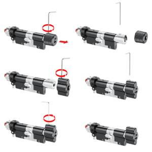
Step 6: Detach the Cylinder Section
1. Use the Allen key to loosen the screws on the relevant cylinder body.
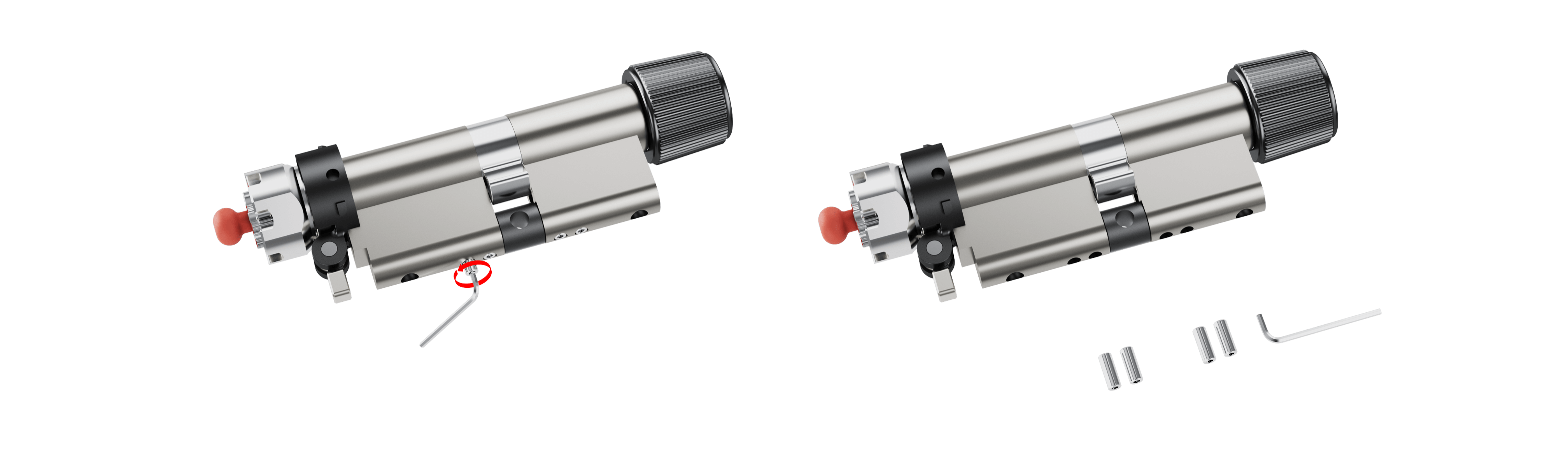
2. Carefully detach the cylinder section as shown in the diagrams.
Note: Keep the screws in a safe place for reassembly.
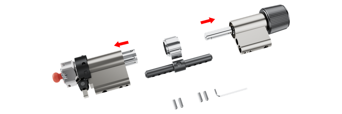
Step 7: Adjusting the Modular Cylinder
Your cylinder can be extended with 5 mm extensions.
- Add extensions to one or both sides.
- Maximum: 2 × 5 mm (10 mm) per side.
- Extensions can be uneven (e.g. 5 mm one side, 10 mm the other).
Examples:
- 35/35 base → up to 45/45 (90 mm total)
- 45/45 base → up to 55/55 (110 mm total)
- 55/55 base → up to 65/65 (130 mm total)
See the diagram below before starting. It shows the final assembly layout and how the cylinder extensions integrate with the full cylinder.
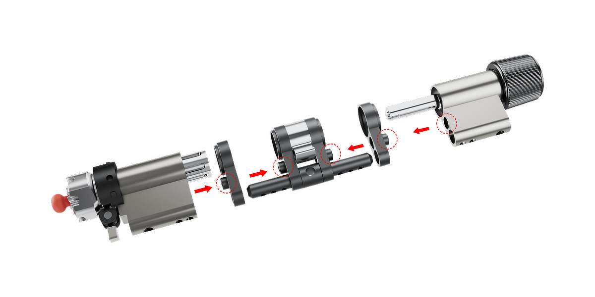
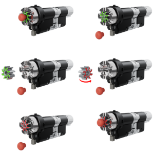
Step 8: Assembly the Extended Cylinder
1. Cylinder body: Place the cylinder extension(s) on the cylinder body if needed or skip to Step 2.
Note: Ensure the protruding side of each plate faces the cylinder body.
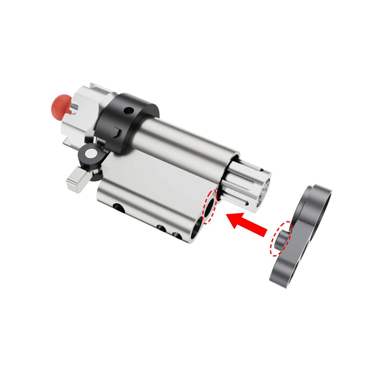
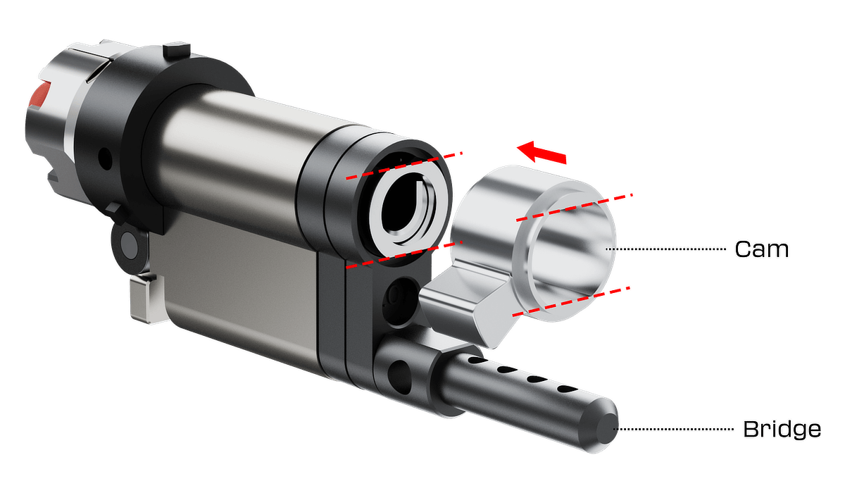
2. Placing the bridge and cam: Attach the bridge and cam to the cylinder body. Make sure the cam is correctly positioned and aligned, as shown by the arrows in the diagram.
Note: If this side doesn’t require an extension, place it in its standard position.
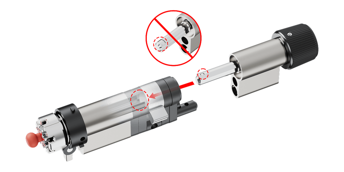
3. Final Assembly: Add the required cylinder extension(s), or omit if this side doesn’t require one. Insert the opposite side of the cylinder into the extension(s) and rotate the knob as shown in the diagram until all internal components align correctly, allowing both sides of the cylinder to connect smoothly and securely.
Step 9: Secure the Assembly
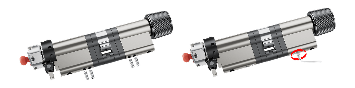
Use the preinstalled screws provided to secure the key modules onto the cylinder body. If a screw is lost, there are four extra screws included.
1. When inserting the screw for the first time, be very careful to ensure it is properly aligned with the thread.
2. Tighten the screws securely, but avoid over-tightening to prevent damage to the cylinder.
Step 10: Test the Cylinder
1. Insert the key into the external side of the cylinder to check for smooth operation.
2. Verify that the key rotates freely and that there is no obstruction or stiffness.
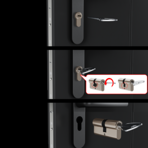
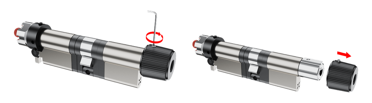
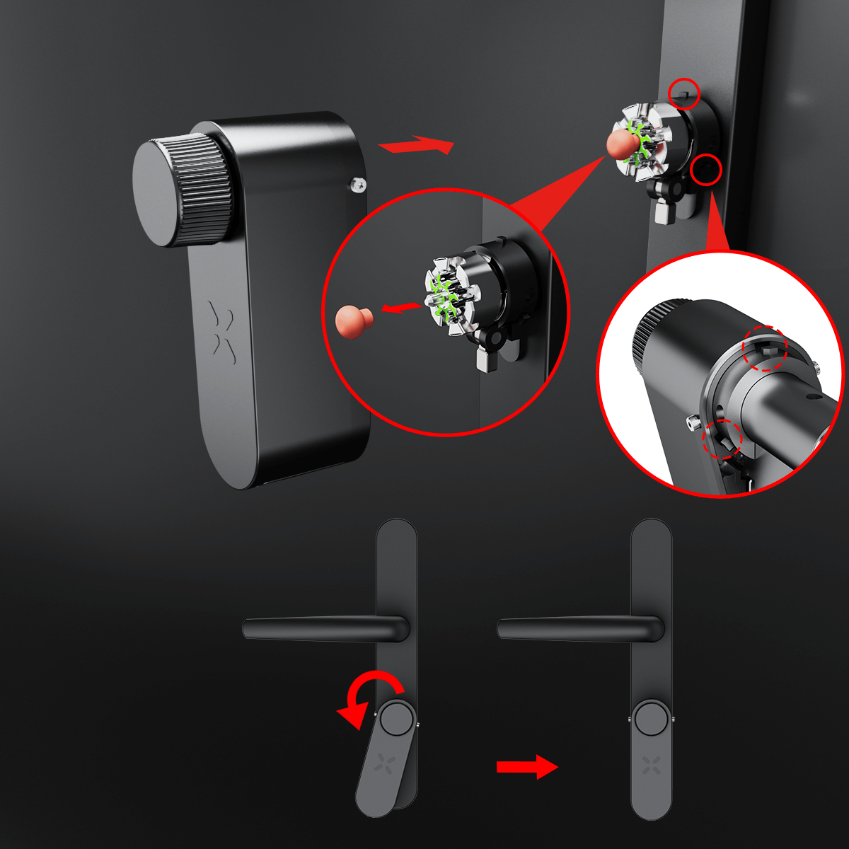
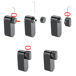
Step 11: Detach the Knob
Use the provided Allen key to loosen and remove the screw securing the knob. Carefully detach the knob from its base.
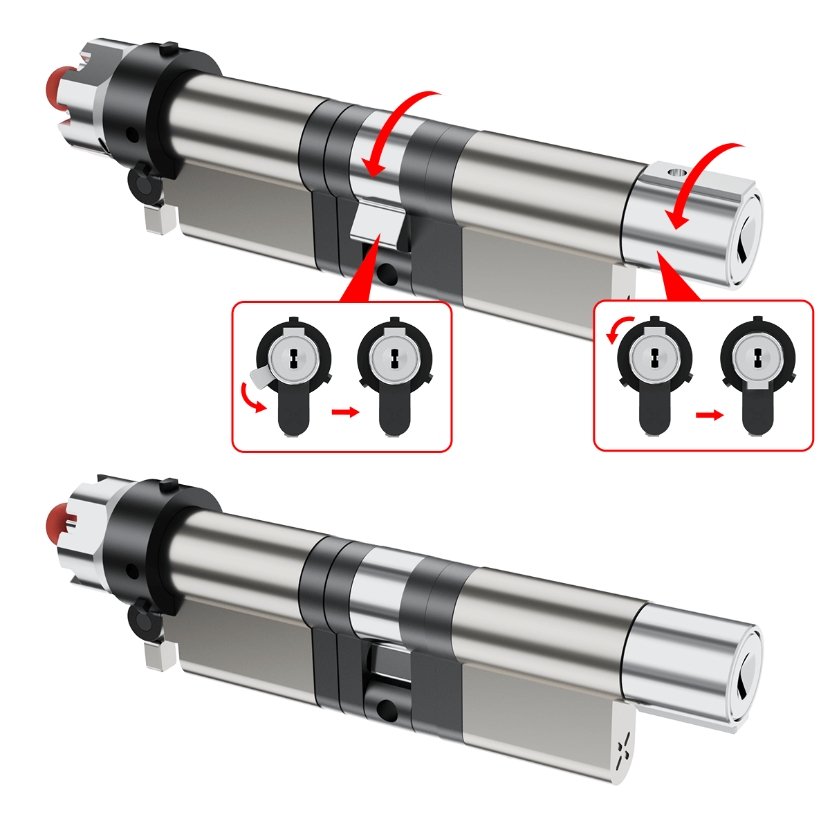
Step 12: Preparing for New Cylinder Installation
Ensure the new cylinder body is properly aligned with Cam '1' and Knob Housing '2'.
Rotate the cylinder as shown in the diagram to achieve the correct orientation for seamless integration into the lock mechanism.
Note: Incorrect alignment may prevent proper integration into the lock mechanism.
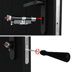
Step 13: Installing the New Cylinder:
- Position the New Cylinder: Insert the new cylinder into its designated position in the door, ensuring proper alignment.
- Secure the Cylinder: Using the provided M5 steel bolt, with a length at least equal to the lock backset plus 10 mm. Hand-tighten the lock screw to secure the cylinder before using a Phillips head screwdriver for final tightening. Ensure the cylinder does not protrude more than 3 mm from the door surface and install safety furniture on the door in front of the cylinder to prevent tampering.
Note: Avoid over-tightening to prevent damage.
Step 14: Identifying Gear Positioning:
The smart lock is installed on the inner side of the door.
Gear Positioning:
- If installed on the right side, the gear should face green.
- If installed on the left side, the gear should face red.
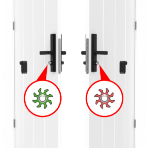
- Flipping the Gear (if needed):
- Remove the gear holder.
- Flip the gear if necessary to match the correct indicator position.
- Reattach the gear holder securely until final removal in Stage 17.
Note: The gear holder is a temporary support to prevent the gear from falling during installation. It will be removed in step 17.
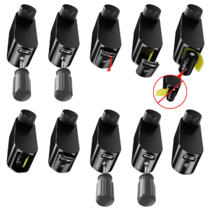
Step 15: Installing the CR2 Battery
- Use a flathead screwdriver to open the Dual-function battery compartment cover by turning it half a turn and pressing down on the latch to release the compartment.
- Insert the battery release tab into the lock, then place the CR2 battery into the BLACK X device, ensuring the positive (+) and negative (-) ends align with the symbols on the battery pull tab. A beep will confirm the device is operational.
- Return the battery compartment cover to its original position with the tab facing outward from the lock. Use the flathead screwdriver to turn the screw back to its locked position.
Note: Ensure that the pull tab is inserted inside the battery compartment. Do not place the battery underneath the pull tab, as shown in the incorrect example.
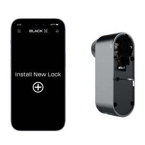
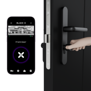
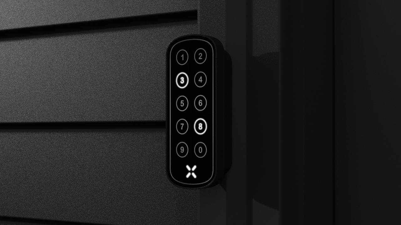
Step 16: Pairing with the BLACK X App


Download BLACK X App from App store or google play and create your BLACK X account before beginning installation.
Ensure your phone’s Bluetooth and Wi-Fi are enabled before attempting to pair.
- Open the BLACK X App.
- click on ‘install a new lock’.
- Name Your Lock or choose a description.
- Create a ‘Home’ to associate with your lock.
- Choose the ‘Home’ for your lock.
- While in "Discovering Nearby Locks" mode, use the Allen key to press the connect button on the BLACK X device.
- When a pop-up for the correct lock appears, click "Connect" to proceed.
- Congratulations! You’ve successfully connected your first lock.
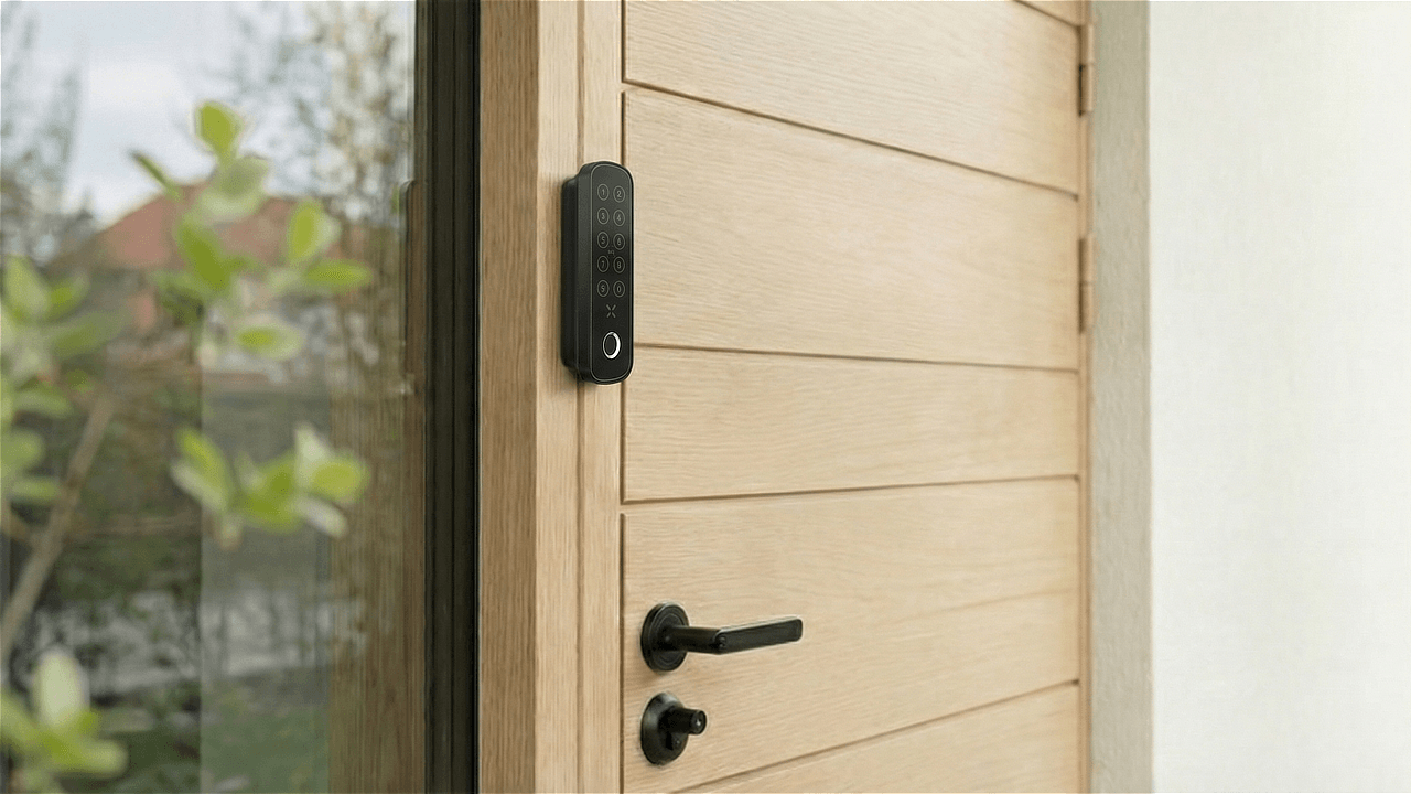
Step 17: Attaching the BLACK X Device
Prepare for mounting: Before mounting the device, use the supplied Allen key to partially loosen the screws on both the left and right sides of the BLACK X device until they are no longer visible from the inside. This ensures proper positioning for installation.

Mounting the Device: Remove the gear holder, as it is no longer needed, and dispose of it. Carefully align and insert the BLACK X device onto the cylinder, twisting it until it securely locks in place. You should hear a ‘click’ when the device is properly positioned. Ensure there is no looseness or movement between the device and the cylinder.
Secure the Device: Use the supplied Allen key to partially tighten the screws on the left and right sides of the BLACK X device, ensuring it is loosely attached but still adjustable. Note: Avoid overtightening at this stage to allow proper alignment of all components.

Mount the external knob: Align the knob with the hole facing upward, then rotate the knob body until it aligns properly. Use the provided Allen key to tighten the screw on the top. Note: Ensure the knob is fully aligned with the hole; if not, the Allen key may turn without securing it properly.
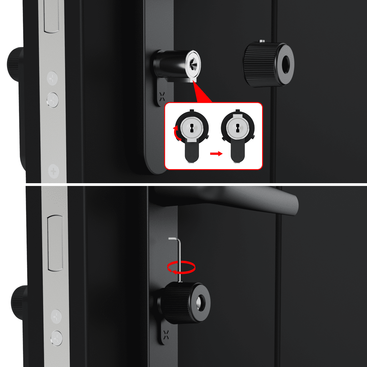
Fully secure the device: Once the knob is correctly mounted, return to the screws on the left and right sides of the BLACK X device and firmly tighten them using the Allen key. Note: Exercise caution to avoid overtightening, as this may cause the opening mechanism to become jammed.
Step 18: Operational Settings and Optional Wi-Fi Bridge Setup (if purchased)
Functionality Test: With the door open, test the new cylinder to confirm it operates correctly.
Note: If you have multiple locks installed, select the new lock for testing.
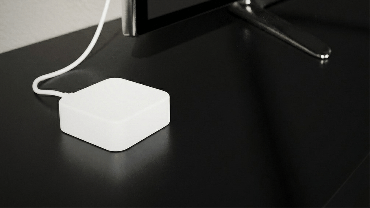
Wi-Fi Bridge Installation: Optionally, install the USB-C Wi-Fi bridge to enable remote access features.
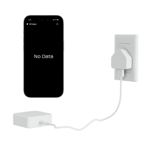
By following these steps carefully, you will ensure a secure and functional installation of your new cylinder and accompanying hardware.
Optional – Knob Replacement
For your convenience, an extra grip knob is included. If you prefer a different grip style, follow these steps:
Inner knob (without a keyhole):
- Use the provided Allen key to loosen and remove the existing knob.
- Install the new knob without a keyhole and tighten it securely.
Outer knob (with one keyhole):
- Use the Allen key to loosen and remove the existing knob.
- Install the new knob with one keyhole and tighten it securely.
Looking for more?
Our assistant can help refine your search, or you can reach our support team directly.