How to install USA Deadbolt Smart Lock - Step by step
BLACK X Smart locks provide enhanced security and convenience, allowing you to control access to your home or office with ease. Whether you're upgrading an existing lock or installing a new one, this guide will walk you through the process of installing a USA deadbolt smart lock efficiently and correctly.
By following these step-by-step instructions, you'll ensure a secure and hassle-free installation. Let's get started!
Pre‑Installation Guide
Before installing your BLACK X Smart Deadbolt, confirm that your door meets the following requirements.
- Door Thickness - Your door must be between 1½"–2" (38–50 mm). Doors outside this range may not be compatible with this model.
- Deadbolt Type - BLACK X is designed to replace a standard single cylinder deadbolt. Your door should have an exterior key cylinder and an interior thumb turn. It does not replace mortise locks, multi‑point locks, or rim locks.
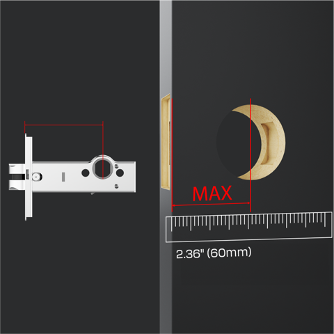
- Backset Measurement - Your door must have a backset of: 2.36" (60mm) Measure from the edge of the door to the centre of the keyhole.
- Door Alignment - Ensure the door closes correctly before installing the lock. Check that:
- The latch moves freely
- The door closes smoothly
- The strike plate aligns with the latch If the door does not close properly, adjust the strike plate before installing the lock.
- Required Tools - You may need the following tools:
- Phillips screwdriver
- Flathead screwdriver
- Measuring tape
- Drill (if installing a new strike plate)
- The Allen key required for installation is included in the box.
- Smartphone Requirements - To use the smart features you will need:
- iOS 13 or later
- Android 7 or later
- Bluetooth enabled
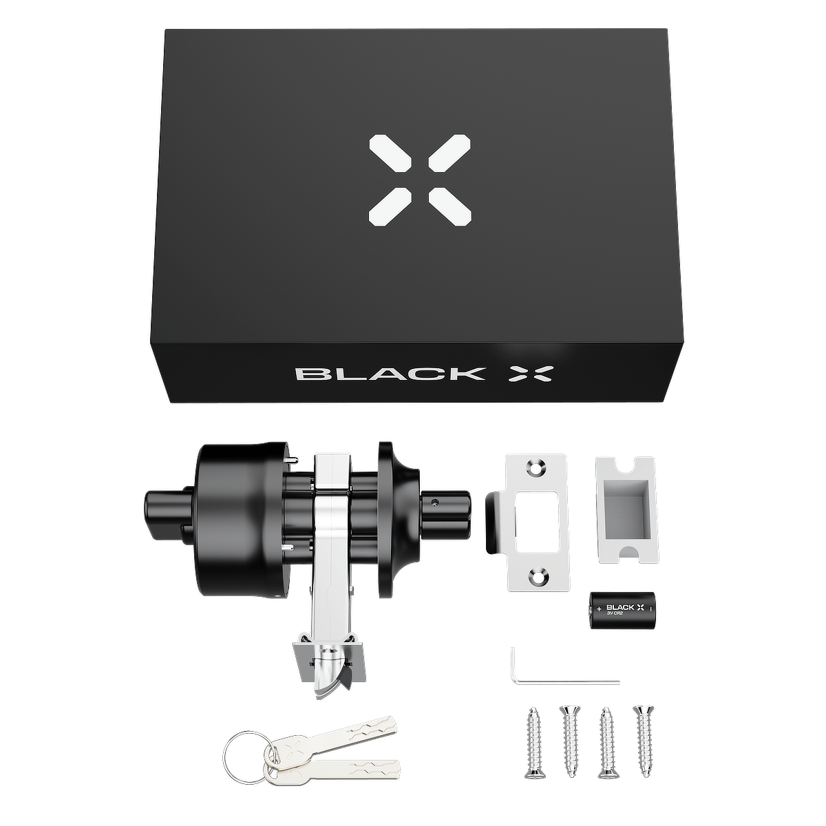
Step 1: Unbox and prepare components:
Before installation, open the package and identify all components. Lay them out for easy access.
Hardware components:
1x BLACK X deadbolt
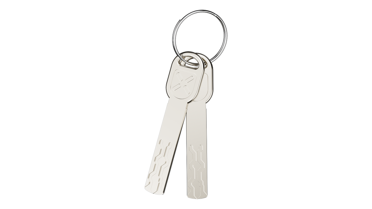
2x Mechanical Access Keys
Box 1:
1X Strike box
1X CR2 3V Battery
Box 2:
1x Allen key
1x Strike plate
4x M4 x 0.71" (18mm) Screws
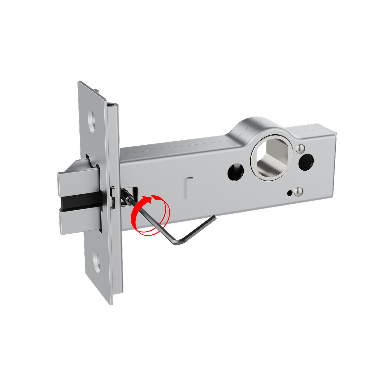
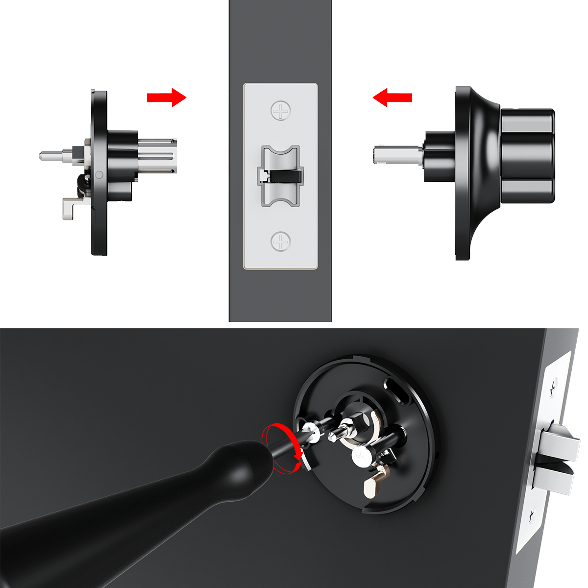
Step 2: loosen the screws
- Insert the supplied Allen key into the screw socket.
- Turn the Allen key counter-clockwise to loosen the screw.
- Repeat the same process for the screw on the opposite side of the lock.

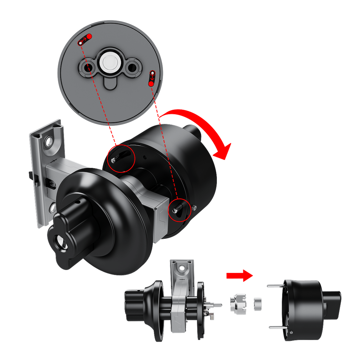
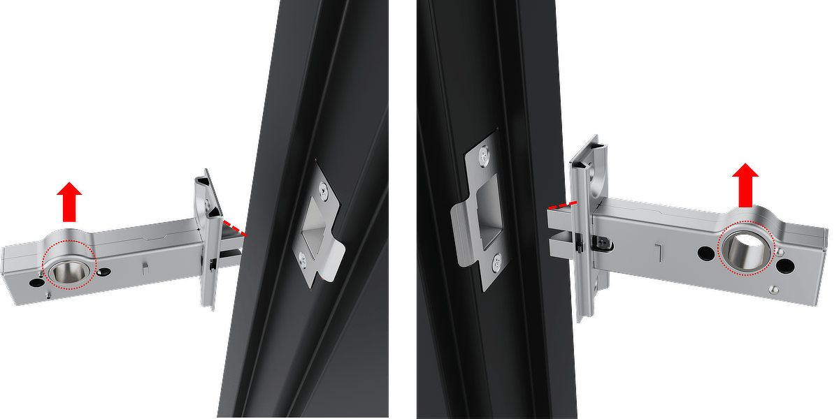
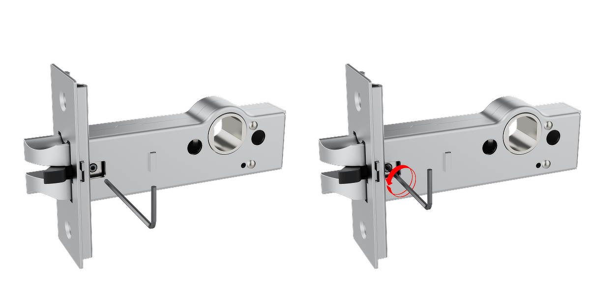
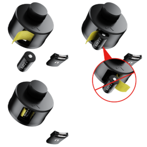
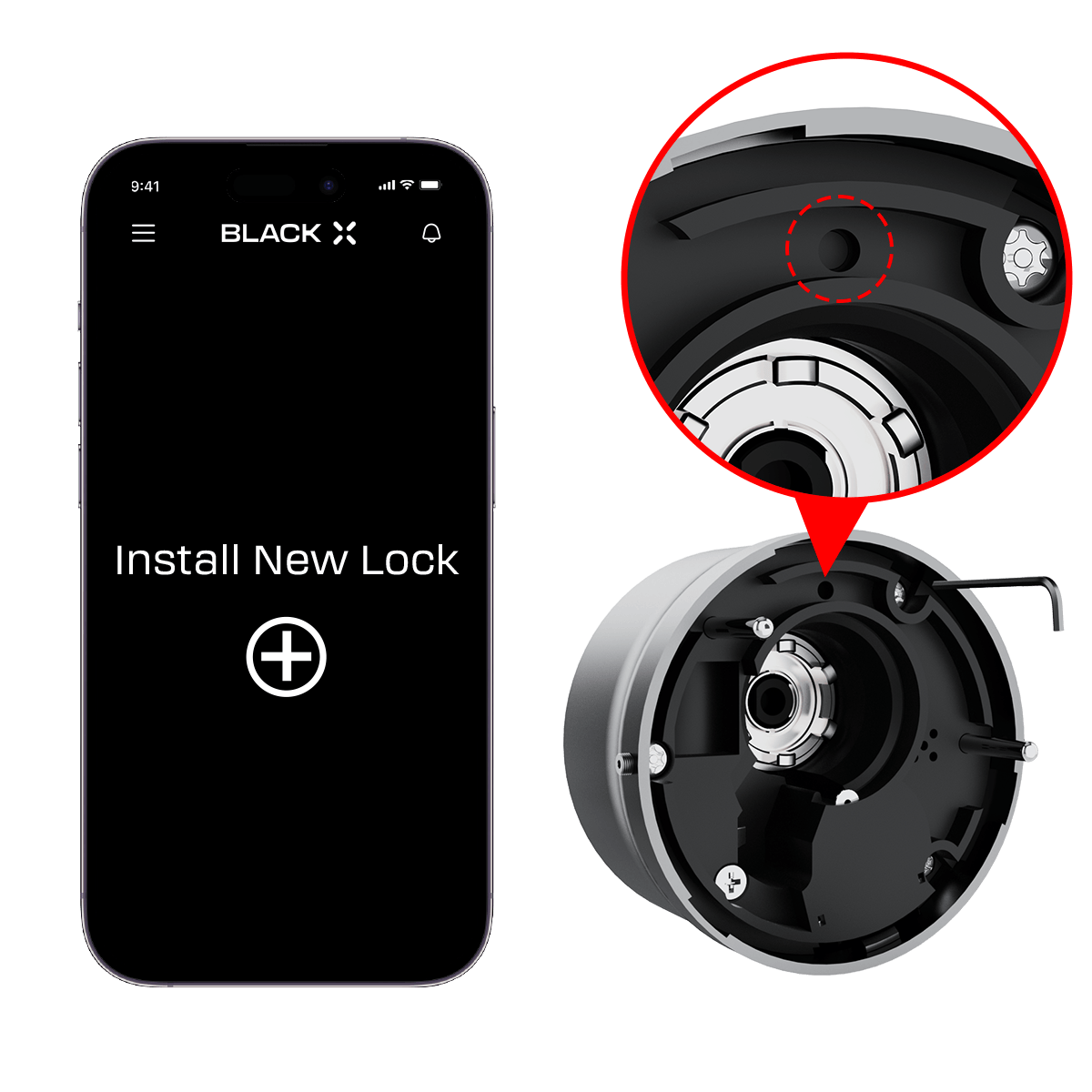
Step 3: disassemble the BLACK X mechanism
- Rotate the BLACK X mechanism counter-clockwise to loosen the body. Note: Refer to the arrows in the diagram for guidance.
- Carefully separate the lock body and ratchet housing as shown in the diagram.
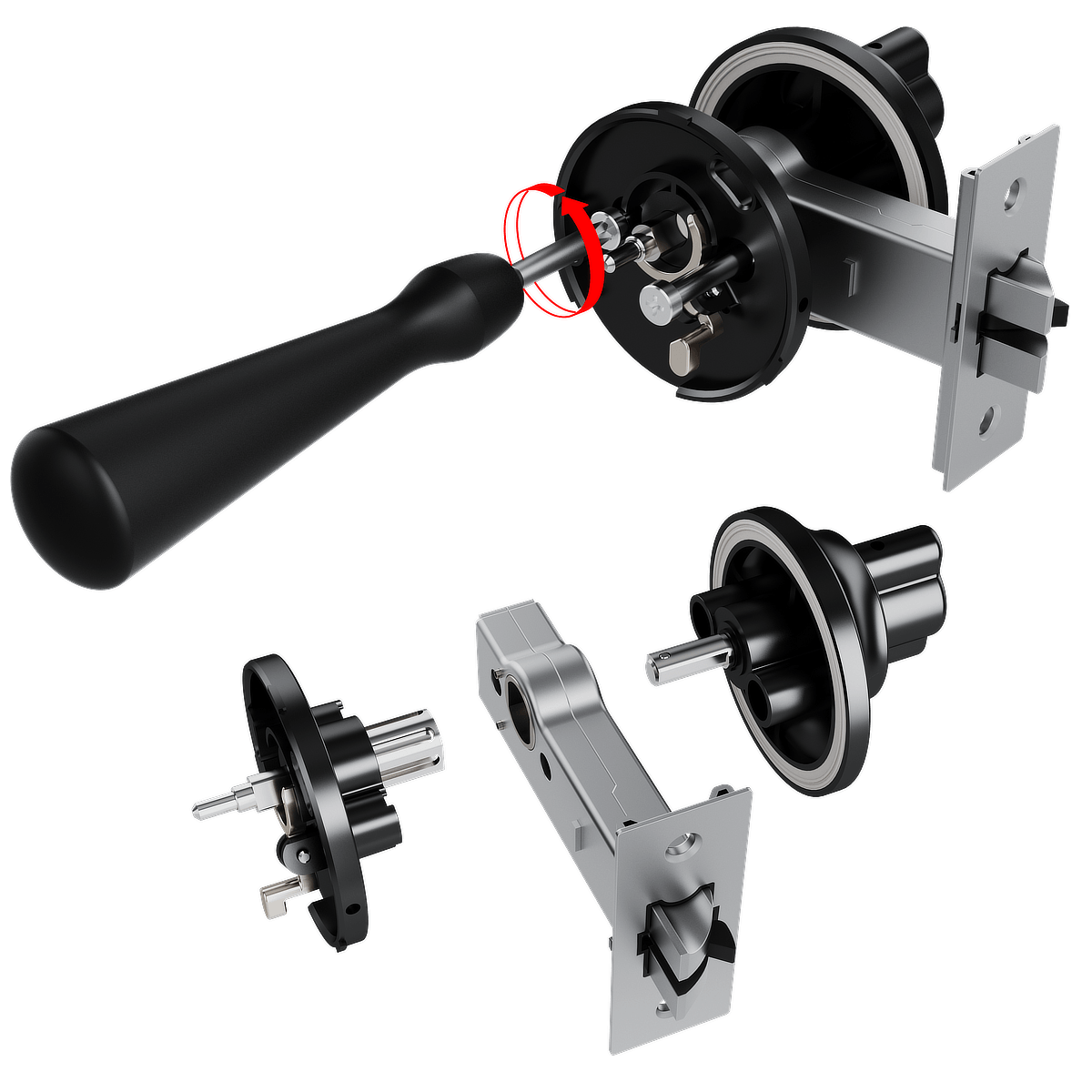
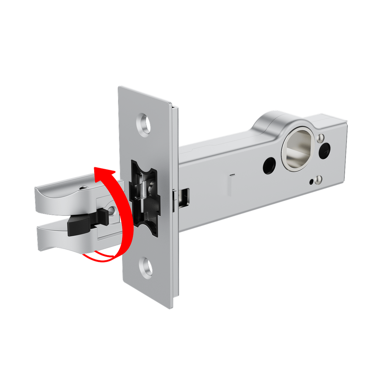
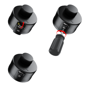
Step 4: Remove the Fasteners
- Insert a screwdriver into the designated fastener slots, as illustrated.
- Turn the screwdriver counter-clockwise to loosen and remove the fasteners.
- Once the fasteners are removed, gently detach the components, following the directions shown in the diagram, to fully separate the lock for assembly preparation.
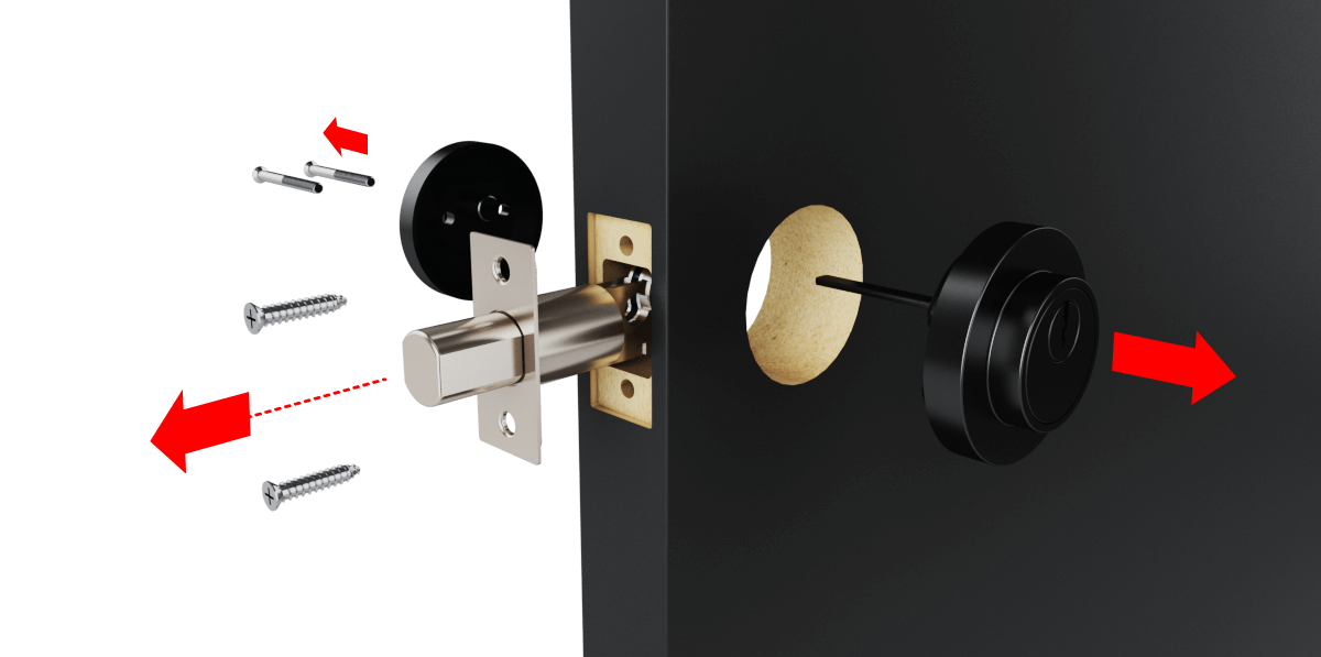
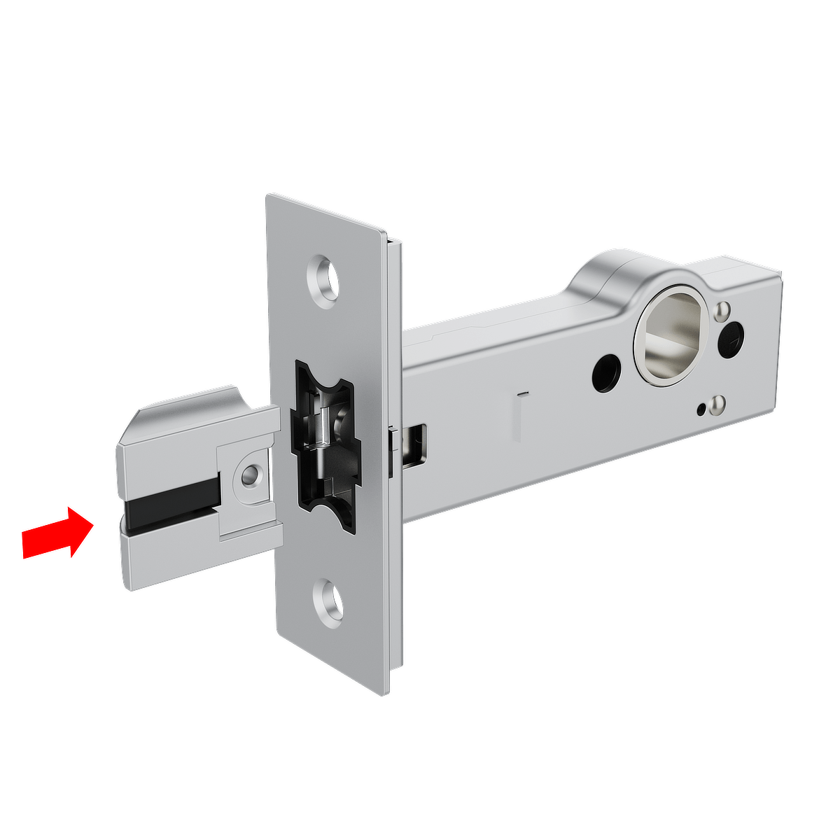
Step 5: Extracting the existing Cylinder:
- Use a screwdriver to remove the screws securing the existing Lock.
- Carefully pull the cylinder straight out of the lock housing.
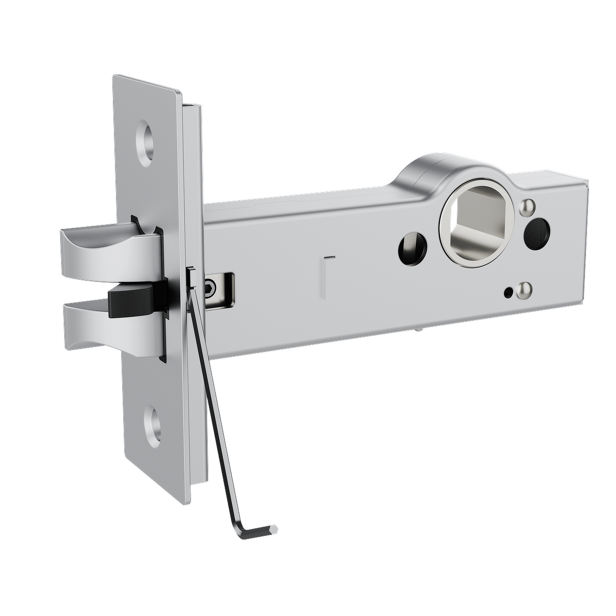
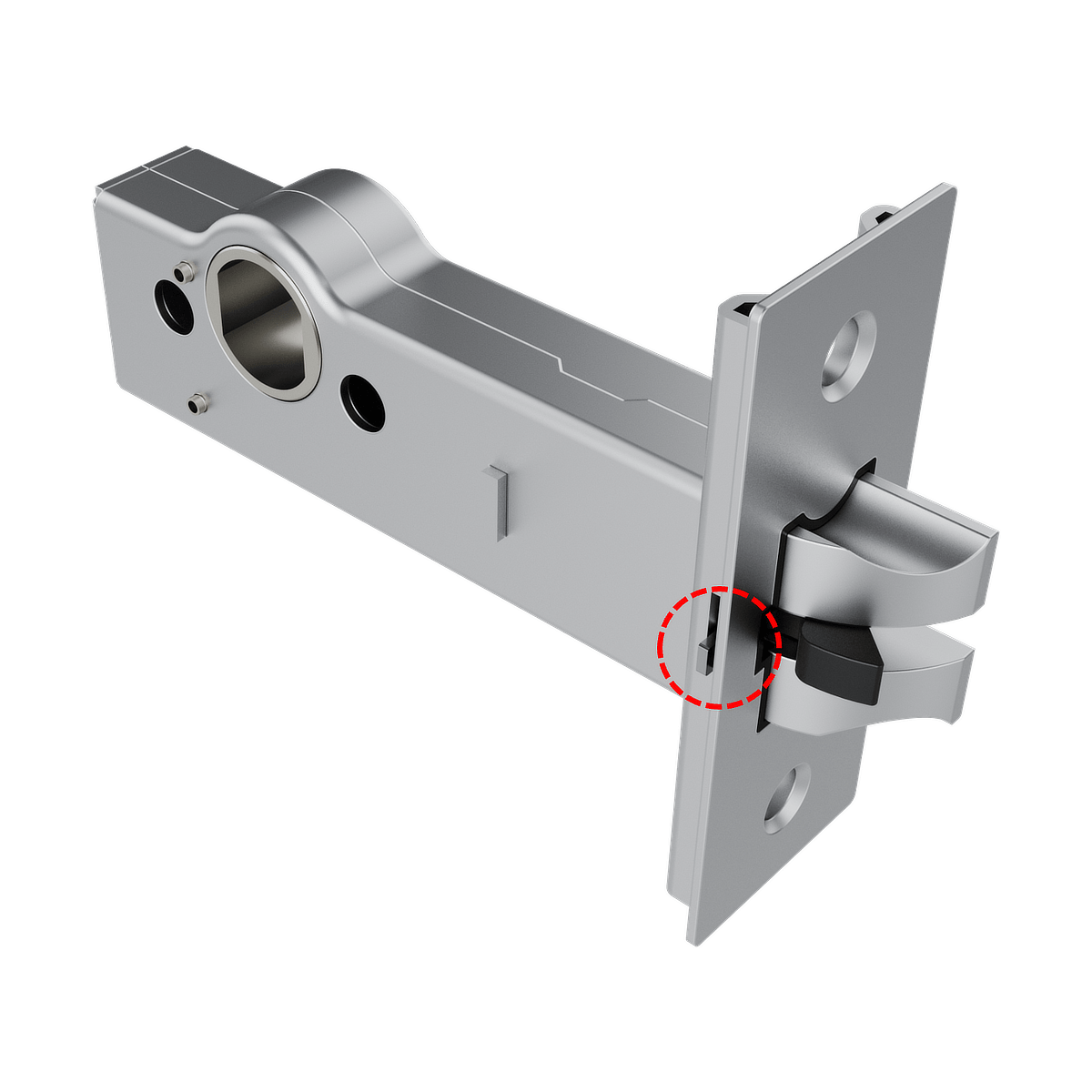
Step 6: Check Latch Orientation
Before installing the cylinder, check that the latch orientation is correct.
Ensure the top mark on the latch housing is facing upward, as shown in the illustration.
Check the latch position:
• The slanted side of the latch must face the door frame (strike plate).
• The flat side must face the interior side of the door.
This orientation allows the latch to retract smoothly when the door closes.
If the latch is correctly positioned, continue to Step 7.
If the latch is facing the wrong direction, follow the instructions below to reverse it.
Reversing the Latch Direction
1. Locate the release tab on the slanted side of the latch.
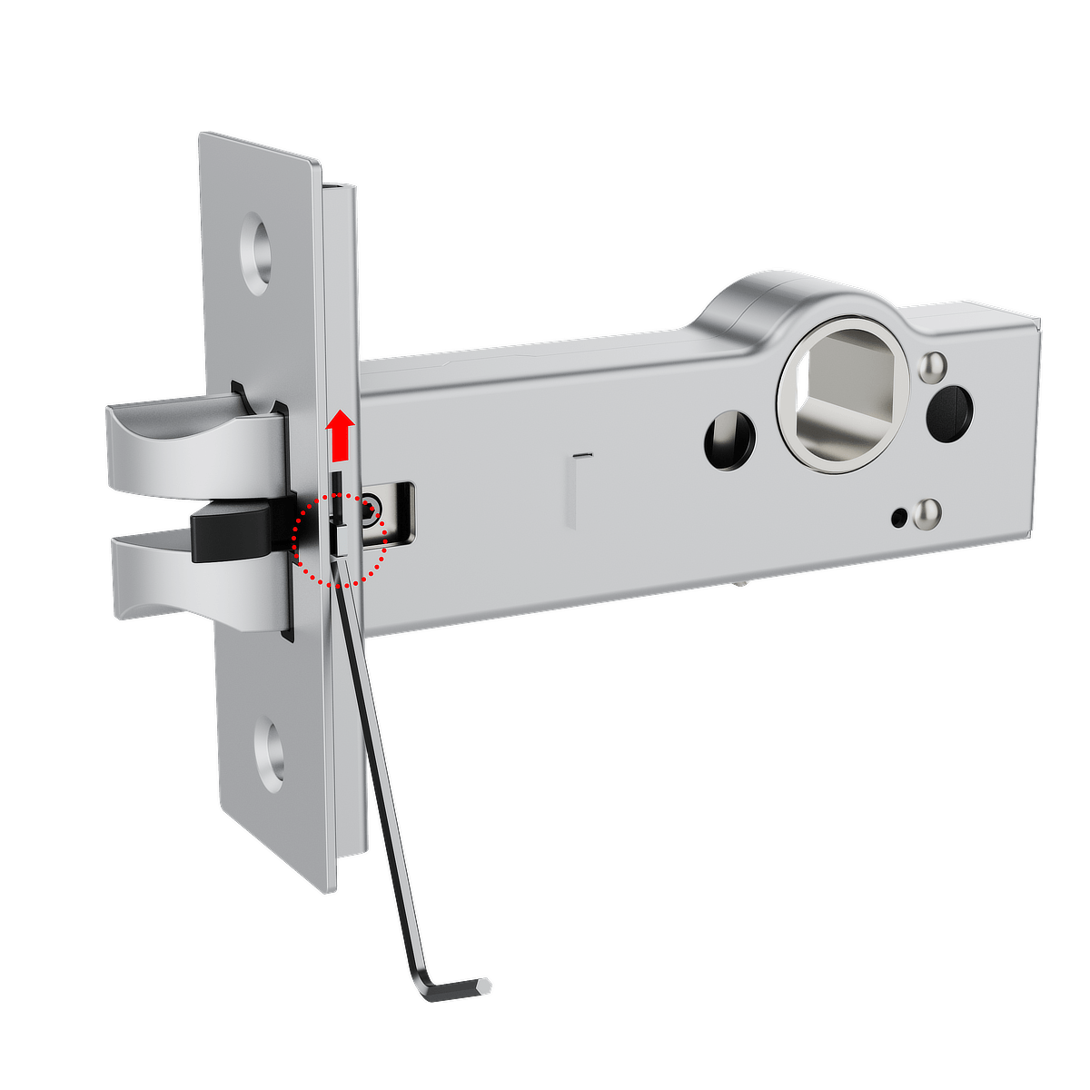
2. Lift the release tab to unlock the latch mechanism.
3. Using the Allen key, loosen the Hex socket screw.
4. Remove the latch from the housing.

5. Rotate the latch 180° to the correct orientation.
6. Insert the latch back into the lock housing.
7. Tighten the screw to secure the latch.
8. Push the locking slider (black piece) toward the latch until it is fully inserted.

9. Push the release tab down to secure the latch mechanism.
⚠ Important
• Ensure the locking slider is fully inserted.
• If the locking slider is not fully pushed in,
the release tab cannot lock correctly.
Do not lock the release tab until the locking
slider has been fully inserted.

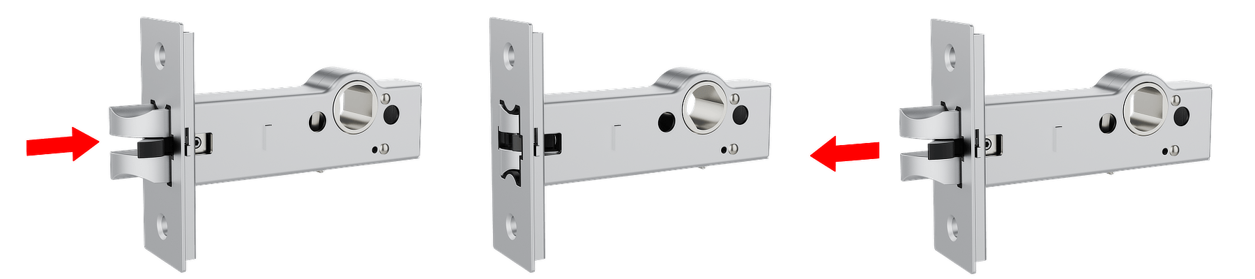
Step 7: Latch Function Check
Before inserting the cylinder, confirm the latch operates correctly.
Press the latch and ensure that it retracts fully into the housing.
Release the latch and ensure it returns smoothly to its original position.
- If the latch operates correctly, continue with the cylinder installation.
- If the latch does not retract fully or does not return properly, repeat Step 7 and ensure the latch, release tab, and locking slider are positioned correctly.
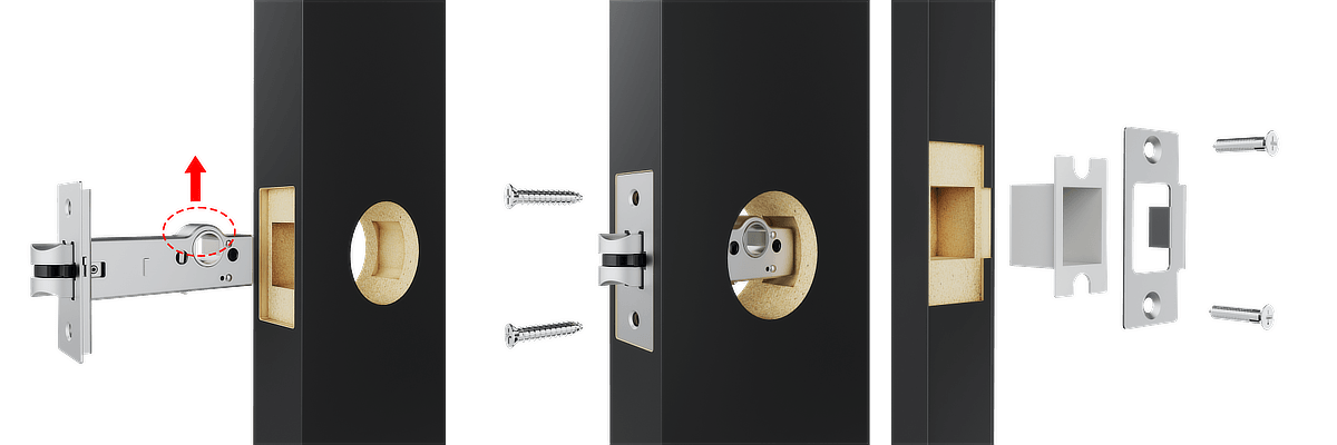
Step 8: Install the Cylinder
1. Slide the cylinder straight into the lock housing on the door, as shown in the diagram. Ensure the cylinder is fully aligned with the screw holes.
Note: Insert the cylinder in the orientation shown in the diagram, with the latch facing upward.
2. Secure the cylinder by tightening the 2 supplied screws.
3. Insert the strike box into the door frame, then secure the strike plate using the supplied screws.
Step 9: Installing the CR2 battery
1. Use a flathead screwdriver to open the dual-function battery compartment cover. Turn the screw half a turn and press down on the latch to release the compartment.
2. Insert the battery release tab into the lock. Place the CR2 battery into the BLACK X device, ensuring the positive (+) and negative (-) ends align with the symbols on the battery pull tab. A beep will confirm the device is operational.
3. Return the battery compartment cover to its original position with the tab facing outward from the lock. Use the flathead screwdriver to turn the screw back to its locked position.
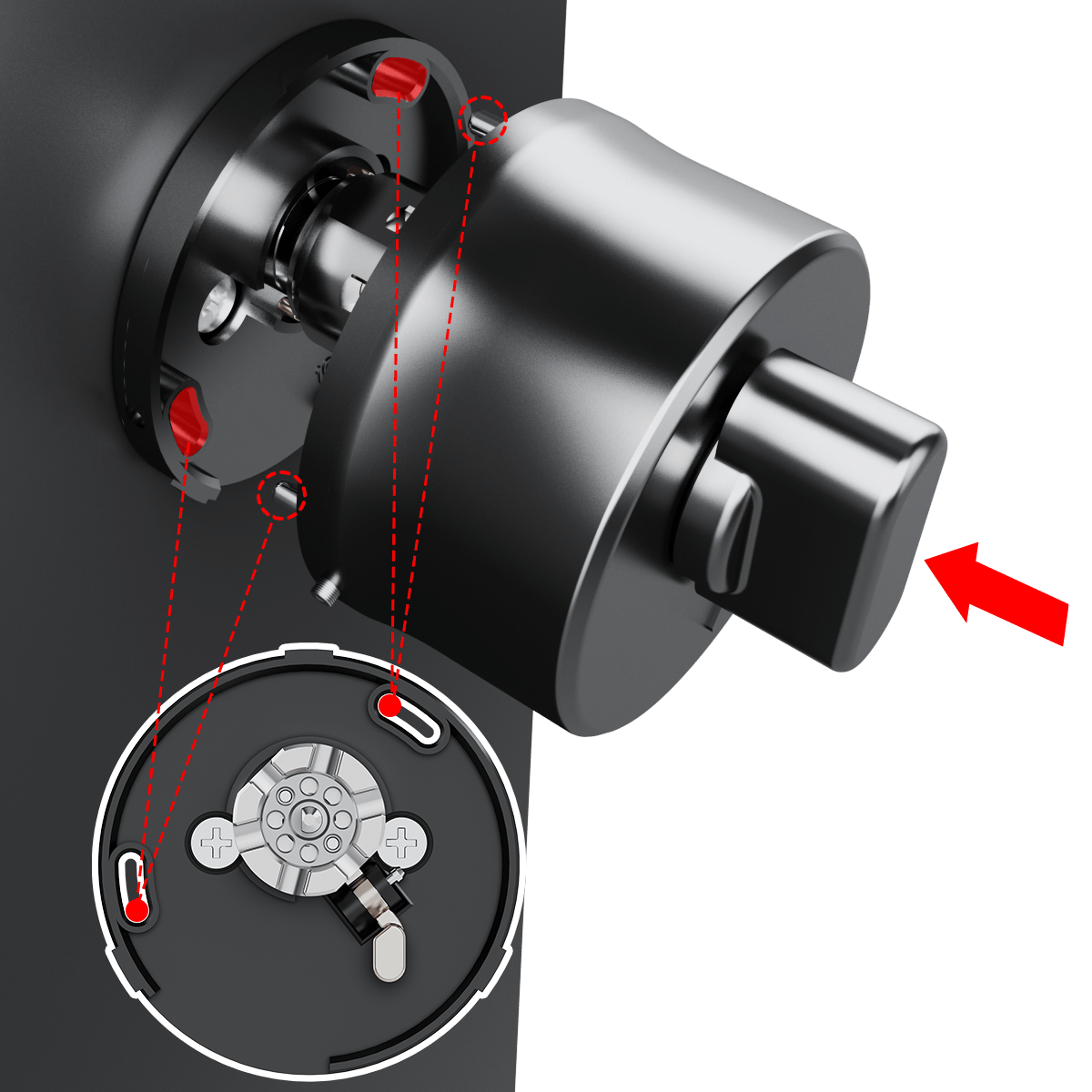
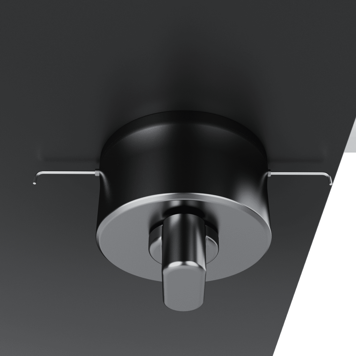
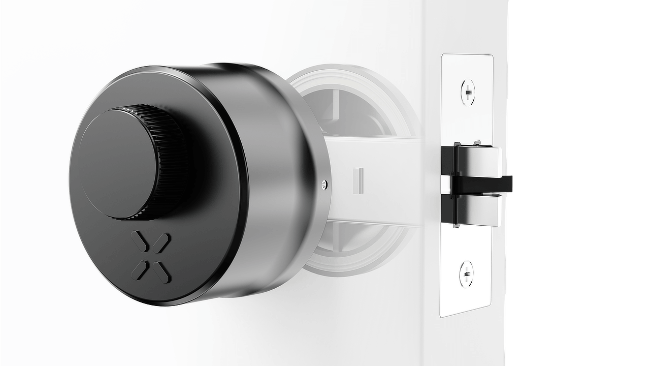
Step 10: Attaching the BLACK X Deadbolt Device
1. Insert the lock mechanism through the door as shown in the diagram.
2. Align the components with the corresponding holes on both sides of the door.
3. Slide the lock mechanism fully into place, ensuring it fits securely within the door structure.
4. Tighten the screws to secure the lock in place and ensure proper alignment and functionality.
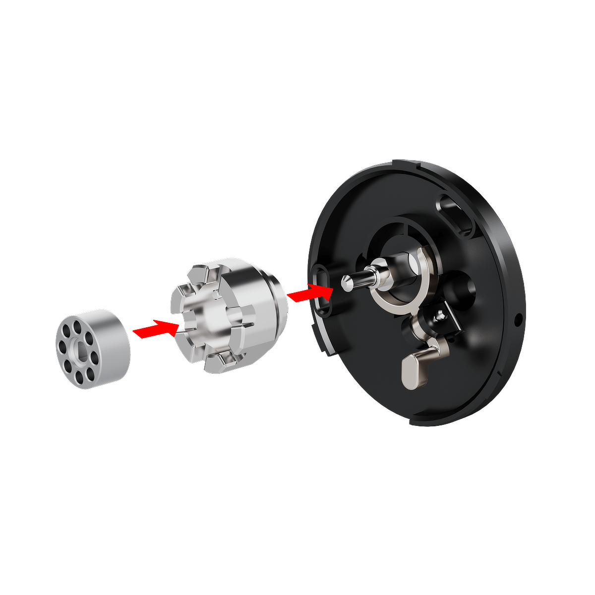
Step 11: Gear Assembly
The smart lock is installed on the inner side of the door.
- Insert the gear into the house gear.
- Align the gear assembly with the pin on the lock body.
- Slide the assembly onto the pin until fully seated.
- Confirm that the gear assembly is properly positioned.
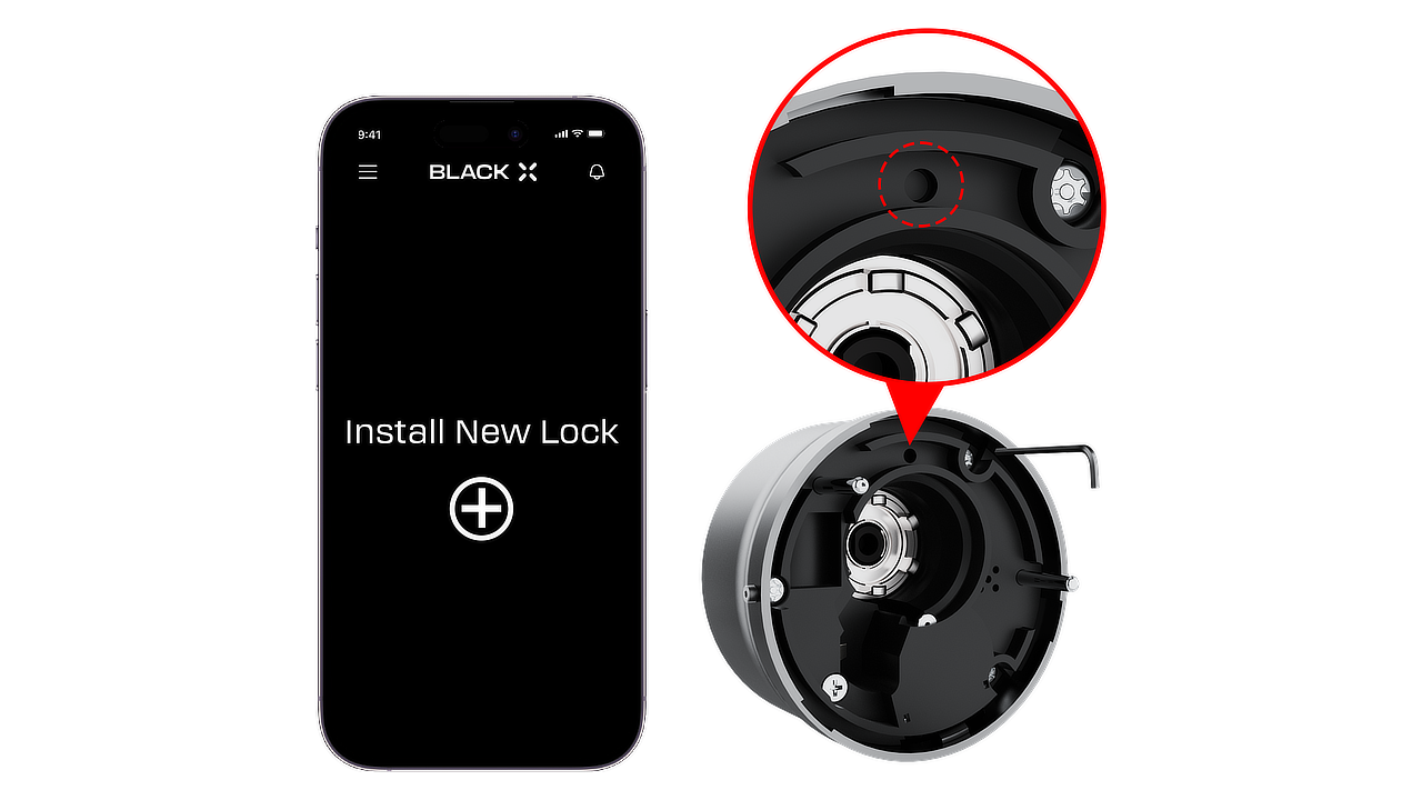
Step 12: Pairing with the BLACK X App


Download BLACK X App from App store or google play and create your BLACK X account before beginning installation.
Ensure your phone’s Bluetooth and Wi-Fi are enabled before attempting to pair.
- Open the BLACK X App.
- click on ‘install a new lock’.
- Name Your Lock or choose a description.
- Create a ‘Home’ to associate with your lock.
- Choose the ‘Home’ for your lock.
- While in "Discovering Nearby Locks" mode, use the Allen key to press the connect button on the BLACK X device.
- When a pop-up for the correct lock appears, click "Connect" to proceed.
- Congratulations! You’ve successfully connected your first lock.
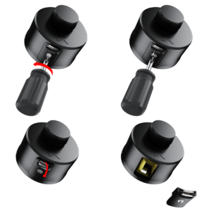
Step 13: Final Assembly
1. Align the two parts of the lock assembly, as demonstrated in the illustration.
2. Rotate the assembly in the direction indicated by the red arrows to securely connect the components.
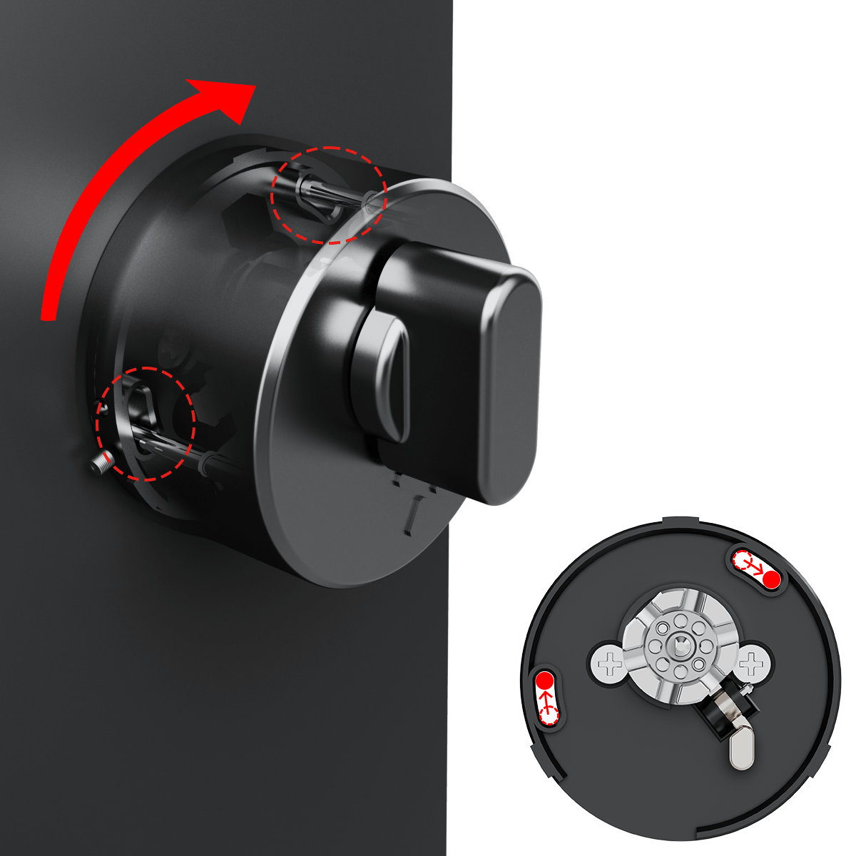
3. Once aligned, ensure the mechanism locks into place by rotating it slightly to confirm a tight fit.
4. Use the Allen key to rotate the screws clockwise and tighten them on both sides.
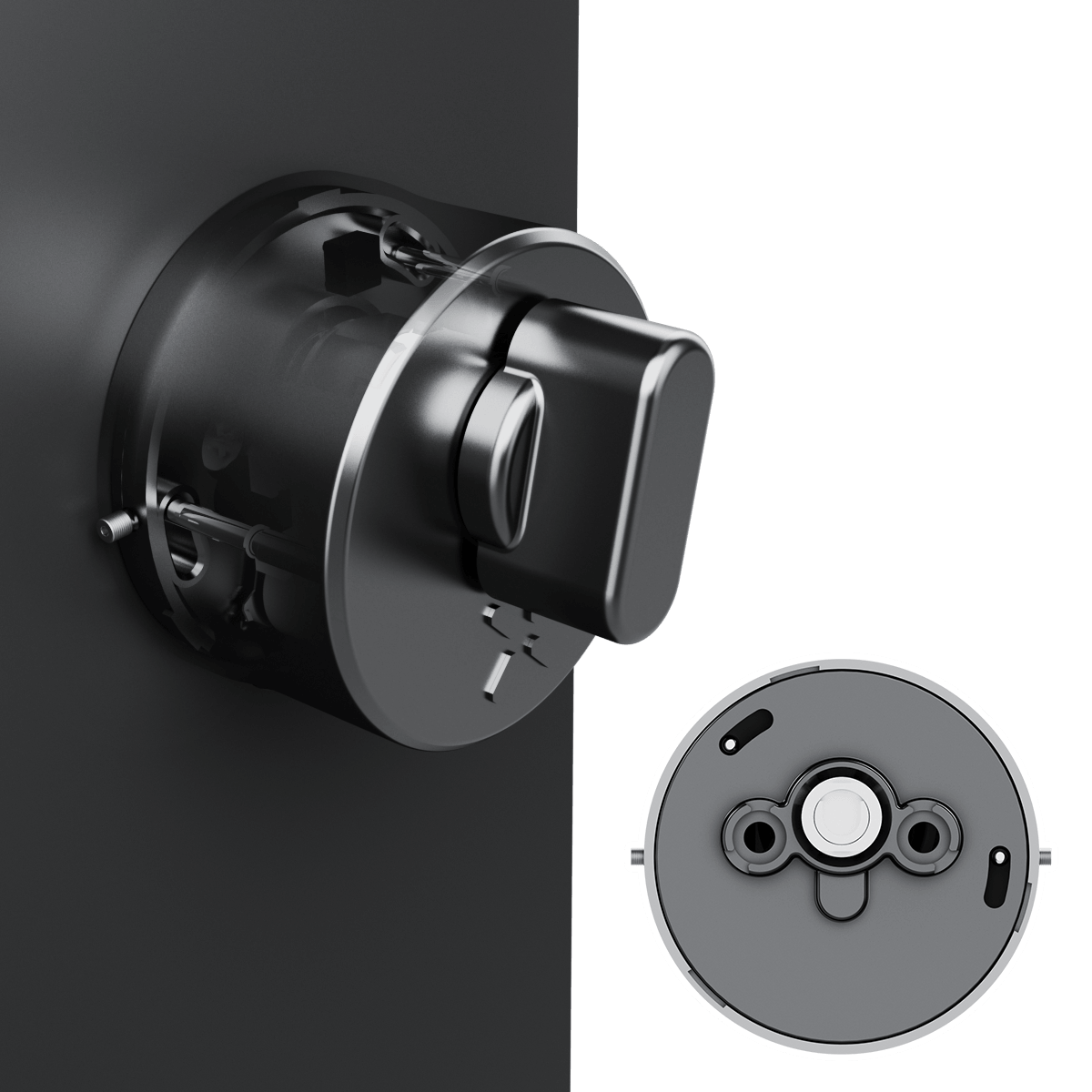
Step 14: Functionality Tests and Optional Wi-Fi Bridge Setup (if purchased)
A. Door Closing Test
Before completing installation, verify that the latch moves freely.
1. Press the latch bolt and confirm it moves smoothly into the latch housing.
2. Release the latch and confirm it returns fully to the extended position. The latch must move freely without sticking or binding.
If the door does not close or latch properly after installation, check the following:
• The slanted side of the latch faces the strike plate.
• The top mark on the latch housing is facing upward.
• The latch bolt retracts fully when pressed.
• The locking slider is fully inserted.
Incorrect latch orientation may prevent the door from closing or latching correctly.
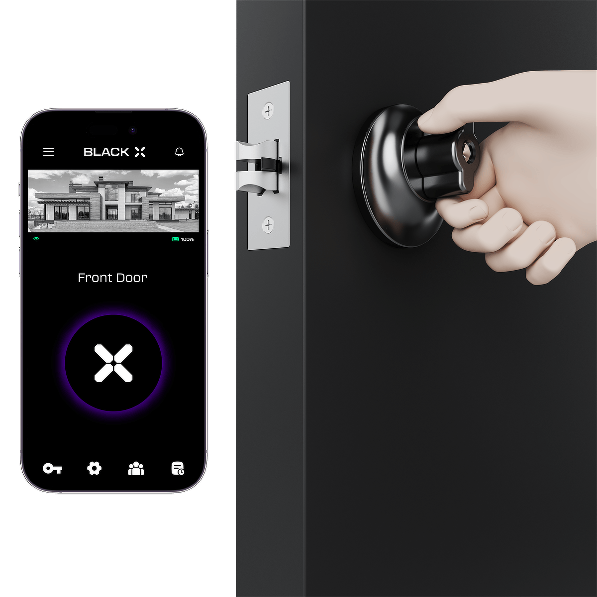
B. App Function Test
With the door open, use the BLACK X app to activate the unlock command
and confirm the lock operates correctly.
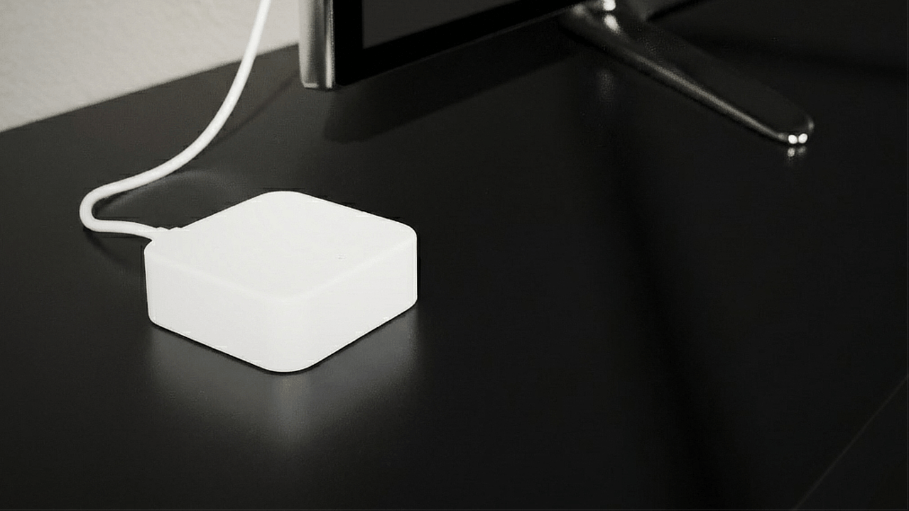
C. Optional Wi-Fi Bridge Installation
If purchased, connect the USB-C Wi-Fi bridge to enable remote access features.

Looking for more?
Our assistant can help refine your search, or you can reach our support team directly.